Monday, January 29, 2018

Simple Accumulator Charger Circuit

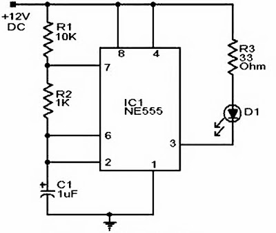
Simple Accumulator Charger Circuit, is a tool that can be used to store electrical energy in the form of chemical energy. We can easily find batteries on motor vehicles and such. In a battery there is an electrical cell in which there is an electrochemical process that is reversible or can be reversible with high efficiency. In other words, the process can convert electrical energy into chemical energy, or chemical energy into electrical energy.That is why the energy of the accu can be recharged by the charge, If the chemical energy in the accu is exhausted, it can be charged again using electrical energy which will be converted and stored in the form of chemical energy.
As the name suggests, the accu charger is used to recharge the energy in the expired battery. The series we are going to share this time is a simple sequence that utilizes some basic electronics components. For more details you can see in the following reviews.

Accumulator charger circuit scheme:

 Accumulator charger circuit scheme

All the components listed in the schematic of the series can be found in the electronics components stores that are near your home. But if you want to shop online electronics components.

If you want a simpler circuit try to make a regular accu charger circuit that is not automatic. The required components are also simpler and fewer. Here is a schematic of a simple accu charger circuit that is not automatic.

battery charger

So little information about Simple Accumulator Charger Circuit. Hopefully this information can provide benefits for loyal readers and good luck.

Circuit for Siren Police Car or Ambulance

Circuit for Siren Police Car or Ambulance, Indeed we can buy ready-made sirens in electronics stores. There are sirens 3 sound models, 6 sirens sound, and siren 9 sounds. So one siren can sow different types of sounds. The price is also very diverse depending on the features offered.
But there's nothing wrong if we try to make their own siren using some simple electronic components that can easily be encountered in the market. Counting is more cost-effective than buying ready-made sirens, as well as to hone our skills in becoming an electronics technician.

Actually to make another police siren or siren is not difficult because the circuit is simple and does not require many components. The series of police car sirens that we will share this using 3 volt DC voltage, 6 volts, or 9 volts that can be directly obtained from batteries or motorcycle or car batteries.

This police car siren circuit uses two transistors. The first transistor is a 2N3904 type transistor and a TIP30C type transistor. As for the output using 8 ohm speakers. Okay just follow the schematic drawings of the series complete with a list of required components.

car siren scheme

Component:
Resistor 51k Ohm x2
Resistor 1,5k Ohm x2
Capacitor 0,1uf/25V
Capacitor 47uf/25V
Transistor 2N3904
Transistor TIP30C
Speaker 8 Ohm

Well, that was a series of police car sirens that could be made with simple electro components. You can modify the circuit or component to get the desired results both in terms of volume and type of sound. Hopefully useful and bye.

Automated Car Parking Sensor Circuit

Automated Car Parking Sensor Circuit, For people who are just learning to drive a car, parking is one of the hardest parts. Because when parking backwards, the driver must be careful and careful in estimating the position of the car to the parking space just by looking in the rearview mirror. Take it easy, because you can create an electronic circuit that can help you park your car backwards.

The working principle of this circuit is actually very simple. The sensor is only in charge of detecting the distance between the rear bumper and the wall or objects that block it. When the distance is too close, the sensor will issue a notice to the rear bumper of the car does not hit the wall and cause damage.
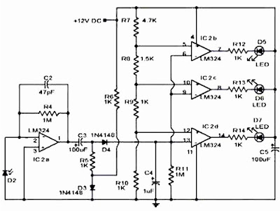
The series of parking sensor of this car consists of two parts, namely the transmitter and the receiver. Here is a complete car parking sensor circuit scheme that you can make reference to make your own simple car parking sensor.

Picture transmitter circuit scheme:

transmitter circuit scheme

Picture receiver circuit scheme:

Receiver circuit scheme

The output of this series is 3 pieces of LED. When the car and wall bumpers are 30 cm apart, then 1 LED will light up. When the car and wall bumpers are 25 cm apart, 2 LEDs will light up. And when the car and wall bumper is 20 cm away, 3 LEDs will light up, and the driver must stop the car.

That way the car and wall will not happen. Oh yes, both circuits use DC voltage of 12 volts. You can take it from a car battery or make your own power supply circuit. What is certain in the circuit using some of the ICs that are easy to find in the store electronics components around you.

Sunday, January 28, 2018

HP Charger Circuit For Car

HP Charger Circuit For Car is an electronic device that always accompany wherever we go, especially as a business that is always related certainly HP must always be active wherever located not in the car. Because if it can not be contacted then the opportunity to earn an income will disappear just because we can not be contacted. This time there is a series of hp charger in the car that you can make your own. The main component of the HP Charger Series in this Car is the LM2596T IC.

Picture circuit hp charger for car:
hp charger for car circuit

Component:
IC1: LM2596T 5.0
D1: 1N5408
D2: 1N5824
C1: 100nF
C2: 470uF / 25V Low ESR
C3: 220uF / 25V Low ESR
R1: 1K 1/4 w
R2: 470R 1/4 w
L1: 33uH / 3Amp 150 KHz
F1: fuse 4A
J1: DC socket
J2: USB (A) sockets
J3: USB (A) sockets
S1: SPST on / off switch
LED1: LED 5mm red color 
LED2: LED 5mm green color

This series can you get into the back of the dashboard so that the car does not look messy and for the usb sockets can be mounted on the dashboard plate so you just use the data cable just to charge your HP. For the monitor there are 2 pieces of LED that you can put also on the dashboard plate. LED 1 for IN so when when the car lock in ON Led 1 position will turn on. LED 2 as monitor OUT.

Seven Segment Driver Series With IC 74HC595

The seven segment series is a series that serves to control the 7 segment display. Seven segment itself is basically a combination of several LEDs that form a digital number pattern. To turn seven segment in accordance with the desired number then it takes a series of seven segment drivers. The seven segment driver series is actually optional, can be used can not. If not using 7 segment driver circuit, 7 segment connection can be directly connected with microcontroller controller. A series of seven segment drivers is required if the display used is large enough, so the voltage required to power 7 segments is also large. For such cases a 7 segment driver is required as an intermediary between the microcontroller with 7 segments.

display seven segment

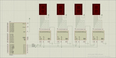
There are so many types of seven segment series that you can use. You can find references in google about this segment 7 segment driver. On this occasion I will discuss one of a series of seven segment using TTL IC type 74HC595. This IC is an IC shift register, its function is to change the input in the form of serial data into parallel data which will be connected to 7 segment display. But this series you can develop for drivers more than 4 digits once you understand the working principle.

seven segment circuit

IC 74HC595 has some input and output pins. The input consists of the following pins:
  • SH_CP, is the clock input pin
  • DS, is the input pin of serial data
  • ST_CP, is the data latch pin
  • MR, is the clear pin output. If this pin is low then the output will be all 0
  • OE, Output Enable pin that serves to enable output
While the output of IC 74HC595 consists of pins Q0-Q7 and Q7 '. Pin Q0 - Q7 is a parallel data output that is inserted serially from the DS pin. While pin Q7 'is a serial output that can be connected with other IC 74HC595, as seen in the picture above 7 segment above.
Serial data inputted through the DS pin, every 1 bit of data must be accompanied by 1 cycle clock. The serial data entered as much as 32 bits, because the above circuit there are 4 pieces IC74HC595 where 1 piece of IC has 8 bits of output data. After 32 bits of data entered, to output the output in parallel concurrently pin ST_CP must be set high then low.
The seven segment series is quite simple and cheap to make. There is one more 7 segment driver circuit that uses IC MAX7219. The principle works more or less the same as IC74HC595.

Simple Power Bank Circuit

Power bank is one of the most important tools for now. This becomes a problem in itself when the smartphone features more sophisticated. Power bank is one solution offered to handle the problem. With the power bank we like to have more backup batteries and very helpful at all when traveling.
Maybe for you fans of the electronics world, see the power bank will certainly be curious. Actually like what is the inside of the power bank circuit? Or how the hell do I create a power bank circuit? Can we make our own power bank? Well, the answer I will explain in this post.

Power bank consists of several main parts, namely as follows:
  1. Battery
  2. Battery Charging Circuit
  3. Charging Gadget Circuit
Battery, is a temporary power storage medium. Battery on the power bank must be a battery that can be charging or recharging. Not disposable batteries such as ABC batteries or Alkaline batteries. Although the battery can actually be used, but can not be re-charging. Batteries used in power banks are usually Ni-MH batteries.
Battery charging circuit, is a series of electronics that serves to manage the charing process on batteries. Ni-MH batteries have special provisions for the charging process. Should not be in-charging. Arusa and voltage during charging process must be in accordance with battery specification. If the charging process is not correct, then the battery will be more quickly damaged. Or usually called baterei has leaked. Well, this battery charging circuit function to keep the current and voltage used to mencharging in accordance with battery specifications. So the batteries become more durable.
Charging Gadget Circuit, is part of the power bank circuit that serves to manage the voltage and current that will be used to mencharging gadgets. To charge the smartphone battery, it should not directly use the output of the battery power bank. Due to battery voltage and power flow of the bank does not match the battery that will be in charging smartphone. Therefore it is necessary gadgets charging circuit to adjust the voltage and output power of the bank.

charger circuit

To make the power bank circuit itself basically only needed 3 main component that I have mentioned above. May need additional switches and led lights as a flame indicator of the power bank. For batteries, you can use batteries used laptop.
For battery charging circuit and gadgets charging circuit you can buy the module in electronic component store. To make this circuit a bit more complicated because the range is quite complex. Therefore I recommend to buy it, because the price is also not expensive. Once the above components are complete, you can start to assemble your own power bank.

Picture scheme of power bank circuit below:
scheme of power bank circuit

You only need to connect the cables according to the above sequence. And if so, please test to do charging to your smartphone. Make sure your circuit is correct before trying it!


Simple Power Supply Circuit Suitable For Beginners

Simple Power Supply Circuit is a must-have on an electronic device. Power supply circuit has the main function to supply voltage for other circuit. In electronic appliances such as TV, Computer, DVD or others need power supply. Power supply is also very needed for you who hobby in the field of electronics. To conduct experiments to make electronic circuits, surely need a power supply as a voltage source. Actually a lot of power supply is also sold in the market in a ready-made form. But maybe the price is somewhat expensive for you. Well, therefore in this tutorial I will discuss the topic about making a simple power supply circuit that you can practice at home. Make sure you understand basic about electronics if you want to practice how to make this power supply circuit.

Parts In Power Supply Circuit:
  1. Voltage Reduction (Step Down)
  2. Rectifier Circuits
  3. Filter Range
  4. Voltage Stabilizer Circuit (Regulator)
Voltage circuit is a circuit that serves to reduce the AC voltage from 220 volts to a lower voltage. As you know, the power voltage in our house is 220 volts AC. To make the power supply circuit, 220 volt AC voltage must be lowered first so that the voltage becomes lower. The voltage drop can use step-down transformer.

Rectifier circuit or commonly called a rectifier circuit, is a circuit that serves to make the AC voltage (back and forth) into DC voltage (unidirectional). This circuit uses a combination of several diodes. There are 2 types of rectifier circuit that can be used to make power supply. Among others are as follows:
  1. Half Wave Rectifier
  2. Full Wave Rectifier With 2 Diodes
  3. Fullwave Waveguide With Diode Bridge
Voltage stabilizer circuit or commonly referred to as a series of regulators, is a circuit that serves to stabilize the voltage at a certain value. This circuit usually uses a special IC regulator. There are 2 types of regulator ICs that are usually sold in the market that is Linear Regulator and Switching Regulator.

Linear regulators are widely used to make simple power supply circuits. Because this type of regulator pretty much sold in the market. This linear IC regulator is usually glowing 78XX or 79XX. Where XX is the regulator output voltage. Example if the desired power supply with output voltage of 5 volts then linear IC regulator used is 7805. If desired is a power supply with 12 volt output voltage, then used is IC regulator 7812.

Image Simple Power Supply Circuit:
simple power supply circuit

The power supply circuit above uses a step down transformer type zero transformer. While the rectifier circuit uses a full wave rectifier type with H-bridge. Then as filter circuit used electrolytic capacitor with value 1000uF and 1uF. For the regulator is used IC type 7812, so the output of simple power supply circuit above is 12 volt with the ability to supply current of 1 ampere. The above circuit you can make at home with plain PCB or PCB holes, so it can be used as a power supply for your experiment!

Sunday, January 21, 2018

Running LED Circuit

Running led is a basic applicative circuit whose usage can be modified in such a way that it can form running letters, drawings or characters running by arranging the led in accordance with our wishes.

Running Led circuit scheme :
running led circuit

Component:
  1. LED
  2. R1=1K
  3. R2-R8=220 Ohm
  4. VR=10K
  5. C1=10pF
  6. IC1=555
  7. IC2=4017
  8. B1=Battrey  9V

Circuit Explanation:

IC4017 is an IC decade counter that outputs high value (logic 1) alternately with timer term corresponding to timer / clock that goes into the IC, as the clock generator we use IC 555 with asatable base circuit, duration of this clock / timer can we set by rotating the variable resistor.


Saturday, January 20, 2018

Automatic Flashlight Circuit

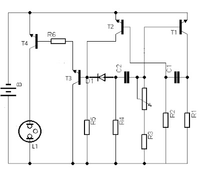
This time we will try to assemble Automatic Flashlight Circuit which is applied to home flashlight. This tool works once to set the flashlight like a bright flame, dim or in accordance with our wishes. Flashlights for special purposes consist of lamps with heavier and longer material, and produce brighter light. Factors to consider when designing a flashlight include light output, durability, and the ability to operate in a special environment. Battery life is also an important factor.

Automatic Flashlight Circuit Image:
Automatic Flashlight

Component:
R1 = 8K2
R2 = 33K
R3 = 4K7
R4 = 8K2
R5 = 5K6
R6 = 390 Ohm
C1 = 47nF
C2 = 47nF
T1, T2, T3 = TUN type
T4 = BC141
D1 = DUS Type
L1 = Lights 4.5-9 Volt
P1 = 100K
B = 6-12 Volt Battery

In assembling this Automatic Flashlight circuit, try to assemble the circuit unit into a flashlight box according to the types and sizes we use. By using a potentiometer as a regulator of light then now we can save energy from the flashlight.

Portable Microphone Preamplifier Circuit

The Portable Microphone Preamplifier circuit is primarily intended to provide the usual stereo home amplifier with microphone input. The power supply from the battery is a good compromise, in this way the input circuit is free of low frequency and the power connection to the amplifier is simpler, due to the absence of power cord and power supply. Using the Stereo Microphone, the circuit capability must be doubled. In this case, two separate levels of control are better than a dual-ganged stereo potentiometer. A low current (about 2mA) will ensure the battery is more durable.

Schematic of Portable Microphone Preamplifier Circuit:
Portable Microphone Preamplifier


Component:
P1 = 2K2 Linear Potentiometer
R1, R2, R3 = 100K 1/4 Watt
R4 = 8K2 1/4 Watt
R5 = 68 Ohm 1/4 Watt
R6 = 6K8 1/4 Watt
R7, R8 = 1K 1/4 Watt
R9 = 150 Ohm 1/4 Watt
C1 = 1uF / 63V Polyester Capacitor
C2, C3, C4 = 100uF / 25V Electrolytic Capacitors
C5 = 22uF / 25V Electrolytic Capacitor
Q1 = BC560C 45V 100mA PNP Transistor
Q2 = BC550C 45V 100mA NPN Transistor
J1 = Jack socket (Mono 3 or 6mm)

How it works :
This circuit is based on low noise noise, high gain two phase PNP fan NPN amplifier transistors, using DC negative feedback through R6 to stabilize proper working conditions. The output level is attenuated by P1 but, at the same time, the stage gain is lowered because of the increased value of R5. The unusual relationship of P1, helps in obtaining high input headroom, which allows to overcome various input sources (0.2 to 200mV RMS for 1V RMS output).

Note:
  • The harmonic distortion is about 0.1% @ 1V RMS output (all frequencies).
  • Maximum input voltage (maximum cursor level set maximum) = 25mV RMS
  • Maximum input voltage (level of cursor control set in middle position) = 200mV RMS
  • Covering the circuit in a metal casing is highly recommended.
  • Simply connect the output of this device to the Aux input of your amplifier through the appropriate cables and connectors.

Thursday, January 18, 2018

Sound Bell Circuit

Sound Bell Circuit is a series of electronic tones or sounds arranged in such a way that it contains rhythm, song, and harmony. In this world almost everyone loves music. No wonder when the music is applied to many devices used by humans, one of them is the bell. There's even a bell that sounds human speech. But on this occasion we will discuss about the bell that can produce or make a sound of music / tone. Sound Bell Circuit is perfect as an exercise for electronics enthusiasts who are still beginners. But for the senior is not prohibited anyway to make it, either made just for a toy or indeed to be a doorbell.

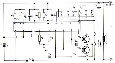
Picture schematic of musical sound bell circuit :
sound bell circuit


Component:
R1 = 100K
R2 = 3K3
R3, R4, R5, R6, R7 = 47K
R8 = 150K
C1 = 33pF
C2 = 10nF
C3 = 10nF
C4 = 10nF
C5 = 0.02uF / 6V
C6 = 0.047uF / 6V
C7 = 100uF / 6V
C8 = 1000uF / 6V
IC = MN6221
TR1 = FCS 9012
TR2 = FCS 9013
S1, S2 = Slide Switch
Speaker = Impedance 4 Ohm

Sound bell circuit like the above scheme is a series of bells that can produce some music sounds that are tailored to its IC type. This circuit is perfect for door bell. The basic component is an IC type MN 6221 which has 16 pins / feet and is amplified by two transistor type FCS 9012 and FCS 9013. Okay, good work and good luck.

Rat Repellent Circuit

Rats repellent circuit is one application of electronic circuit in everyday life.Now with a series of electronics rat repellent it will be one alternative to overcome various problems caused by rats. This tool is an environmentally friendly tool, this tool can also be used as a distributor of hobbies and tinkering with electronics circuits. The electronic components needed to make rat repellent are not much, cheap and easy to find in electronics stores. The circuit can be made on a PCB.

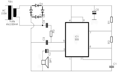
Here is the picture of the circuit scheme :

electronic rats repellent circuit

Component :
R1=1K
R2,R3=15K
C1=1nF
C2=1uF/16V
C3=10nF
C4=220nF
C5=1000uF/16V
D1-D4=1N4001
IC1=555
TR1=Trafo 6V/200mA
SP1=Tweeter

The mouse electronics circuit is simply an oscillator that emits ultrasonic waves in the 20 - 40 KHz frequency range. The resulting ultrasonic waves will not be heard in our ears but will be very disturbing to the ears of mice. For us there is no effect, but the effects experienced by rats will feel very powerful.

Use loudspeaker from peizo electric or tweeter shape speakers to make ultrasonic frequency more effective. Electronic rat repellent is effective for a room with a maximum of 200 m² from the exact placement. Can be placed for example in the upper corner of the room the frequency can spread throughout the room without a hitch. Turn on continuously to keep the mice do not come again, do not worry about the consumption of electricity because the electricity required is low enough.

Tuesday, January 16, 2018

Unique Alarm Circuit

Judging from its name "Unique Alarm Circuit", this alarm is unique. Because this alarm works when the room is dark. The mode of operation of the theft at home (office) is usually by extinguishing the lights so that they can leluada run the action. That is why this alarm circuit is created.

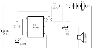
The unique alarm circuit scheme below:
unique alarm

Component:
R1=100K
R2=1M
R3=Trimpot
R4=LDR(Light Dependent Resistor)
C1=1000pF
IC1=NE555
B1=Baterrey 9V
Buzzer

The Unique Alarm Circuit is actually a dark detector circuit that can be used to generate an alarm sound when the light is in the darkroom. This circuit uses Timer IC NE555. LDR is used for light sensing. When the right light falls on LDR the resistance is very low. When there is a hitch to light then LDR resistance increases. At the IC the current is triggered and pushes the buzzer to generate the alarm sound. If the transistors and relays are connected at the output (pin3) of IC1 instead of buzzer, the electric appliances can be activated as light.

Insomniac Recovery Circuit

The Insomniac Recovery Circuit is a new alternative in the effort to deal with this sleepless taker. This circuit is a simple circuit that produces rain sound effects. The Japanese researchers are the first to suggest that the sound of rain has a relaxing effect. With the help of this simple circuit we can produce a sound of rain that can help to put someone to sleep in case of insomnia.

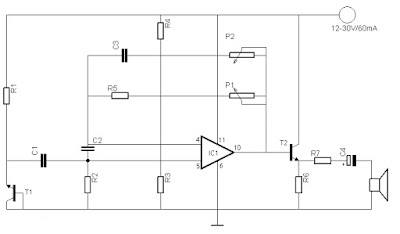
Below you can see and learn the scheme:

insomniac recovery circuit

Component :
R1=270K
R2=100 Ohm
R3=220K
R4=270K
R5=2,7K
R6=220 Ohm
R7=47 Ohm
C1=10nF
C2=0,1uF
C3=1nF
C4=10uf/25V
T1=BC107A
T2=2N1613
IC1=741
P1=47K
P2=100K
LS=4-32 Ohm
Power Supply = 12-30V/60mA

Actually Insomniac Recovery Circuit is a series of rain sound generator. T1 is used as a noise generator and the signal is amplified by IC 741 and through T2, R7 and C4 goes to the headset with low resistance. If you do not want to use headphones you can replace them with speakers with impedance between 4-32 Ohm. With the help of p1 can adjust the sound level and P2 with tone.

Mosquito Repellent Circuit

The development of the world of technology has been very rapid. So it takes an ability to contribute to these developments. Not only the development of the world of communications technology and information, technology in the field of electronics as the main factors that support the technology can experience the development in just a few months, especially electronic devices that are analog or digital. Making this tool, starting from drawing the scheme and then assembled into a series that can be used to repel mosquitoes of course. Mosquitoes are annoying, especially when the conditions are very disturbing us in our rest time at night, whether it is disturbed by the sound until the bite on our body. With this simple tool hopefully you can repel mosquitoes that exist in our homes.

How the tool works :

According to research, usually the bite is often a female mosquito while the female mosquitoes are not happy if approached by male mosquitoes, if not during the mating season.
This circuit produces high-frequency sounds resembling the sound of male mosquitoes. Therefore the female mosquito will leave.

Here is the circuit scheme :

Mosquito Repellent Circuit

Component :
R1=10k
R2=100 ohm 1/4watt
R3=680 ohm 1/4watt
D1=IN4001
P1=potentiometer linear
C1=0,01mf
Tr1=UJT2646
Tr2=BC548
Ls=tweeter

In making this tool is not easy, as for some obstacles that must be faced in the process of making good from the beginning to the end, such as when designing the layout taken from the electronic scheme which will be drawn on the PCB board.

Friday, January 12, 2018

HOW TO MAKE SMPS FROM GACUN

Before heading straight to the main material, we should first know what is Gacun. If you are an electronics technician who often deals with PSU (Power Supply Unit) TV, then the term Gacun is not unfamiliar. Because the Switching Module of Gacun is often applied if the problem of TV PSU is difficult to overcome.

Kit / Module Power Supply Gacun is a very innovative breakthrough. Can be applied to any regulator including TV, as long as the transformer transformer is still good. With this kit the technicians are very helpful to replace the original regulator circuit.
Gacun Module Kit

In this article we do not discuss more deeply about how to apply / install Gacun for TV regulator, but we will make power supply amplifier by using this Gacun module.

Apparently Gacun is very flexible, in addition to the iron transformer prices soar, until finally Gacun module can be a solution in making SMPS cheap. Supporting components can also be obtained from used goods such as TV mainboard and used computer PSU. Function of Gacun in this application as driver of ferrite core transformer / switching transformer.

The required materials are as follows:
1. Switching regulator module / Gacun
2. Transformer: For the transformer we can roll it yourself or the transformer from the former switching regulator that has been damaged and we use the transformer, the easiest looking former TV regulator and used computer PSU
3. Supporting components include: transistor, capasitor, optocoupler, zener diode, resistors etc.
4. Measuring tool: Multi Tester and LCR meter (if any).

How to make coils and count the number of coils.

Often we make coils that mostly do not understand how many coils should be wrapped and what their inductance values are after the coil and what is the ideal, it is related to the ferrite material, the airgap and the physical size of the ferrite.

The better the permeability of ferrite (Bmax) the less the number of coils, the greater the airgap the more the coil and the greater the physical size of the ferrite the less the number of coils, so with the reasoning obtained conclusion, if one or the three elements are different then the number of coils is of course different.

Well how many coils that fit and efficient? Based on repeated tests the ideal inductance value is 500 μH if we have an LCR meter.

Data wire coil :

NP / Primary Coil = 45 twists (not self-made standard)

NS / Secondary Coil = 2 volts / coil (depending on need)

The size of the diameter of the wire determines the amount of power / ampere obtained.

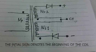
How to wrap wire switching transformer as in the picture, do not upside this one of the keys to successful SMPS Gacun.

schematic coil

Fet Gacun can be paralleled in order to handle large power. However, it is recommended if we have successfully used the standard Gacun.
gacun scheme

WORK PRINCIPLE SMPS SIMPLE CIRCUIT

For this first post we try to learn to know what is SMPS. The easiest term in describing SMPS (Switch Mode Power Supply) is a tool designed for alternative Power Supply. So far we often see the iron transformator as the main component of a conventional power supply.

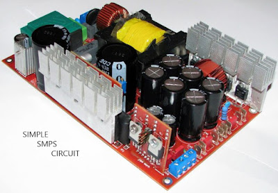
SMPS Circuits

Understanding SMPS
For understanding SMPS has 2 sense that is:

1. Power Supply is a device used to produce or provide a suitable and stable power source in a particular equipment. And usually the available voltage is alternating voltage 220v or can be called with AC, but an electronics equipment requires DC voltage or direction.

2. Switching Regulator which is an electronic circuit used to stabilize the outgoing voltage, such as the outgoing voltage is not optimal, the load current is less than optimal and other

How SMPS Works :

basic circuit smps

~ Submission - change AC input voltage to DC output voltage.
~ Converter - converts DC voltage to output voltage according to need.
Filtering - removes the pulse at the output voltage.
~ Regulation - makes the output voltage stable to the input voltage changes and load changes.
Isolation - Isolate the secondary part of the primary part, with the aim that the chassis of the secondary part if held does not arise the danger of electric shock.
~ Protection - able to protect equipment from over-voltage output and protect power supply from damage in case of error.

The basic parts of SMPS work are as follows:

~ Parts Rectifier. Here the input voltage of 220V AC power is rectified to DC voltage using a diode bridge and 3 large elco filter that is an elco 480V680UF and 2 elco 250V2200UF.
~ Part of enumerator or power-switching. The DC input voltage is enumerated using "on-off power switch" to produce high-frequency pulses of dc pulses. SMPS Inverter welding machines generally work at frequencies from 50Hz to 60Hz. As a power switch can use IC K2611, IRFZ24N and IRF9Z24N.
~ SMPS Controller driver as PWM (Pulse Wave Modulation) pulse generator. As the drive signal for the enumerator used PC 817 IC containing oscillator circuit and PWM as a generator of PWM pulses. There is a SMPS circuit that does not use the SMPS controller driver, in which case a power switching transistor is made to work by "oscillating itself".
~ Switching transformer. The dc voltage that has been chopped has characteristics such as ac voltage so it can be passed by a transformer or inductor to be raised or lowered voltage.
~ The rectification and filtering of the output voltage. The output voltage of the transformer is still a high frequency pulse and then converted to DC voltage using rectifier diode and elco filter.
~ Loop feedback to make the output voltage stable. The feedback loop circuit from the output voltage B + to the primary is used to control the PWM.
~ Comparator circuit as "error detector". A comparator circuit on the secondary part is used to detect if there is a change in the output voltage B +. The comparator works by comparing the output voltage B + with a "reference" voltage (usually a zener diode voltage of 6.8v). The comparator output is a current which is then fed back to the primary through a photo coupler. The coupling using a photocouler aims to isolate the ground of the primary part of the electric shock when held (HOT chassis) with the secondary ground (COLD chasis).

Dimensions and weights.
The ancient powerhouses, especially the most powerful ones, always have large dimensions and heavy weights (capacity determines dimensions and weights), the working frequency is the same as the 50-60 Hz power grid. Whereas SMPS uses much higher working frequency at 50 kHz - 500 kHz. The higher the frequency means the more efficient it works, so it requires a power transformer that is smaller, lighter weight. Thus the size of equipment that uses SMPS as its resources must be more compact size.

Efficiency, Voltage and Output Flow.

The output voltage of the conventional supply depends on the tap on the power transformer. For unregulated types, the output voltage varies depending on the load current. While that is being circulated, the process causes the power dissipation of the transistor (in the form of heat) to decrease the usability, as well as the core conductor losses and the iron core kern is very large, which ultimately all that can produce efficiency only 30-40% only.

At SMPS the voltage is easily set at any voltage and at any current according to the installed capacity without much effect on the dimensions and weights. In SMPS enforcement techniques, regulation is obtained only by adjusting the pulse width, and since the transistor is working completely or completely alive, the heat (and loss of power) is minimal. The disadvantage caused by the capacitor depends only on ESR (equivalent series resistance), so its value is relatively small. Loss of the ferrite core, core conductor and drop-voltage resistor diode. All the so-called contributors are major losers, but with all the losses it can produce a typical efficiency of 60-80%. By improving circuit design, losses can still be minimized, until 95% efficiency is not impossible to achieve.